
| . |
| . |
| . |
| . |
| . |
| . |
| . |
| . |
| . |
| . |
This wear action is very important, because it is often the culprit of several types of failures: (1) tubing splits, (2) corrosion holes & pits, (3) rod
box failure, and (4) rod body failure. The proper diagnosis and documentation of these problems is important to improve the run time of
pumping wells. The mechanisms of these failures related to wear are:
box failure, and (4) rod body failure. The proper diagnosis and documentation of these problems is important to improve the run time of
pumping wells. The mechanisms of these failures related to wear are:
“Corrosion hole or pitting” occurs because of (a)“poor chemical selection or application” or (b) more often when the inhibitor is wiped off by wear allowing corrosion to occur. This “wiping off of inhibitor” is
accomplished by (1) the internal wear from rods or rod guides, or (2) externally by tubing expansion (unanchored tubing). Analysis involves determining either: (1) corrosion is occurring around the entire
circumference due to “poor chemical treatment or selection”, or (2) pitting is occurring along an area wiped free of inhibitors (termed “Corrosion Due to Wear”). This “Corrosion Due to Wear” is indicated by a
roughly straight line of pitting along an area of minor or severe wear (similar to a “tubing split” but wear pattern is not smooth). This wear area is usually about (a) 20% of the circumference for internal wear with no
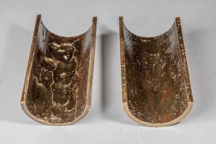
rod guides (30% with certain rod guides), or (b) 20% of external tubing circumference from tubing movement (while pumping without tubing anchor). Figure 2 shows severe pitting along the width of a rod box
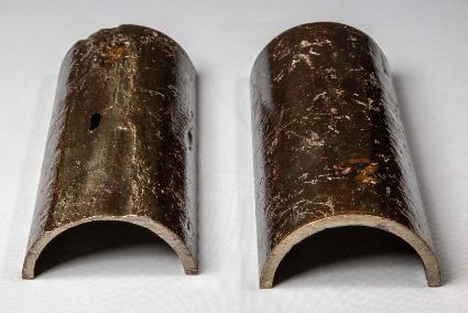
which also was thinner above and along the pitting area (indicating wear wiping off inhibitor since the rest of tubing has very minor corrosion). Figure 3 shows tubing with external wear with pitting along 20% of the
tubing’s circumference (I.D. is the same but O.D. is worn along a straight line indicating tubing wear against casing (unanchored tubing).
accomplished by (1) the internal wear from rods or rod guides, or (2) externally by tubing expansion (unanchored tubing). Analysis involves determining either: (1) corrosion is occurring around the entire
circumference due to “poor chemical treatment or selection”, or (2) pitting is occurring along an area wiped free of inhibitors (termed “Corrosion Due to Wear”). This “Corrosion Due to Wear” is indicated by a
roughly straight line of pitting along an area of minor or severe wear (similar to a “tubing split” but wear pattern is not smooth). This wear area is usually about (a) 20% of the circumference for internal wear with no
rod guides (30% with certain rod guides), or (b) 20% of external tubing circumference from tubing movement (while pumping without tubing anchor). Figure 2 shows severe pitting along the width of a rod box
which also was thinner above and along the pitting area (indicating wear wiping off inhibitor since the rest of tubing has very minor corrosion). Figure 3 shows tubing with external wear with pitting along 20% of the
tubing’s circumference (I.D. is the same but O.D. is worn along a straight line indicating tubing wear against casing (unanchored tubing).
This “Corrosion Due to Wear” mechanism will not normally be solved by (a) installing rod guides and/or (b) redesigning the chemical program (if 80% of area is unpitted, then the problem is not normally due to
chemical type or treatment method). Intermittent rotation with a TSR spreads out the corrosion area to reduce the frequency of the corrosion failures (5 times more metal to corrode around the circumference since
the old wiped off area should be coated with inhibitor after the tubing is turned). Automatic continuous tubing rotation may immediately wipe off the inhibitor and is not recommended if “Corrosion due to Wear”
failures occur. This “Corrosion due to Wear” failure mechanism (absent in some “failure literature”) is a common occurrence since many wells are treated with inhibitors to minimize corrosion rates. Unfortunately,
many “unsuccessful” chemical programs may actually be adequate, but the wiping off of inhibitors by wear causes corrosion holes and lead to unsuccessful attempts to modify the chemical program.
A “rod box failure due to wear” will often have one side of the box worn down until the box fails. Rod guides, which are continuously replaced, may temporarily correct this at the expense of increasing rod stresses
and the circumferential area for corrosion (certain rod guides may wipe off inhibitor from a larger area). One solution is to install Spray Metal Alloy boxes, which are less corrosive and “smoother” (reduces friction
and wear) and are very hard to wear down. With less friction and tubing rotation, the service life may be substantially improved.
A “rod body failure due to wear” will often have one side of the body worn down until body fails due to tension, particularly in deviated wells. This is often temporarily corrected or delayed by Rod Guides. This is not
as big a problem in relatively straight wells because most wear occurs at the rod box site.
as big a problem in relatively straight wells because most wear occurs at the rod box site.
Thus, if the pumping well is properly designed, the prevalent failure mechanism will normally be Wear or Corrosion Due to Wear (often 40 to 80% of the failures). This failure mechanism can be delayed by 400% to
900% by rotating the tubing. Less run time improvement may be expected from the use of the more expensive continuous rotating heads since they could be wiping off the corrosion inhibitors and thereby not
helping the “Corrosion Due to Wear” failure mechanism.
900% by rotating the tubing. Less run time improvement may be expected from the use of the more expensive continuous rotating heads since they could be wiping off the corrosion inhibitors and thereby not
helping the “Corrosion Due to Wear” failure mechanism.
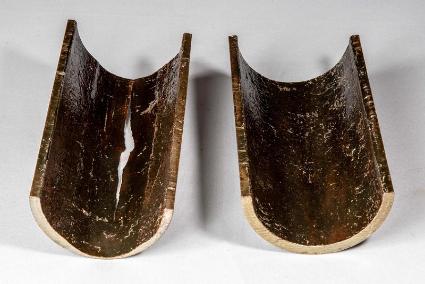
A “tubing split” is often accomplished by the tubing being worn thin and smooth on one side (usually a straight path being 20% of the
circumferential area and the length of the pump stroke) until the pressure in the tubing blows a hole in the tubing. Figure 1 below shows a thin
smooth section on the left half of the tubing with a split at the top {a rod box would fit nicely in the worn area with 80% of the area not worn at
all}. The TSR spreads this wear over the entire circumference to extend run times by potentially 500%.
| Figure 1 |
| Figure 2 |
| Figure 3 |
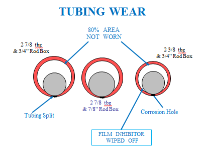
The action of reciprocating or rotating the rods within a pumping well causes wear of the rod string against the tubing (Figure shows relative
sizes of rod boxes in 2-3/8 & 2-7/8 in. tubing with contact area shown and two failure mechanisms). The deviations of a hole will severely
increase the sideways force that increases the friction (drag) between the rods and tubing. However, even “straight holes” will have significant
wear because (1) tubing or rods will lay to the side of the hole (very little room between rod couplings and tubing) and (2) the buckling action of
the rods due to the downstroke or whipping action of the rotating rods. This leads to failures in “crooked holes” to sometimes be in the order of
months (with new tubing), to several years in “perfectly” straight holes.
| The Theory of Tubing and Rod Wear |
| . |
| . |
| . |

| Engineering: |
| Sales: |


| . |
| . |
| . |