| . |
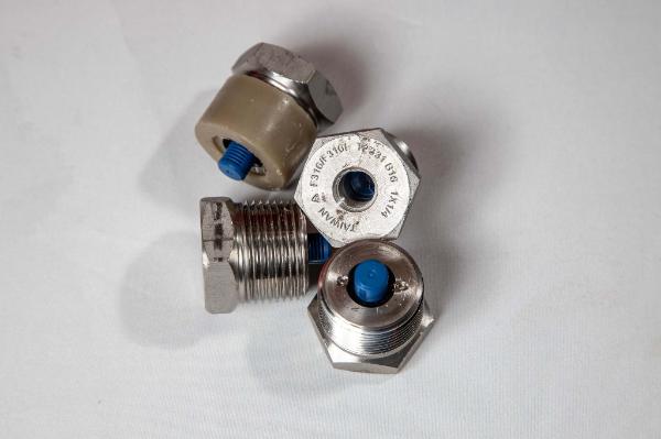
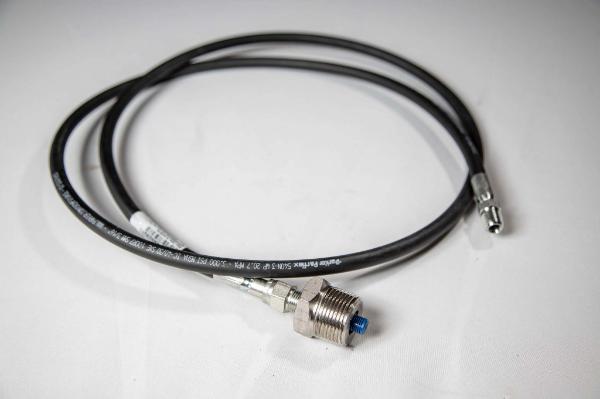
| The SFR restricts the sidestream flush flow of wellhead fluids into the annulus for mixing with continuous chemical injection through the use of a small diameter restrictor line and filter (in lieu of the conventional needle valve choke arrangement). This technique allows sidestream flush volumes to be significantly reduced while also reducing the chance of small particles plugging up the conventional needle valve arrangement. In a field comprised of 700 wells utilizing continuous chemical injection, the SFR allowed for the pumping units to be slowed down thus reducing failure rates and saved around 625 kilowatts of electricity while improving chemical operation. Read more on actual field test results and economics HERE. Continuous chemical injection in a pumping operation (rod pumps, PCPs, submersible pumps) normally require a portion of the producing wellhead fluids (sidestream flush) to be mixed with chemical and placed back down the tubing annulus. The sidestream flush rates are normally restricted by a needle valve or ¼ in. valve. However, chemical operations normally require only 5 to 10 barrels per day (BPD) of sidestream flush, which would require around a 0.025-inch orifice diameter equivalent in the choke. In practice, the operator will often choke the well back to a point where the needle valve will hopefully not plug up (from sand, scale, or other particles), which often results in a larger choked flow area and high sidestream flush rates. In actual field tests, around 300 wells (at +/- 1600 feet) were found to have sidestream flush rates averaging 75 bpd per well. An SFR design was implemented to restrict fluids to around 10 bpd per well, which resulted in saving 1.2 HP per well ($450/well/year), and reducing pumping failures (by slowing down the pumping units and a better chemical operation). Field wide implementation of the SFRs reduced electricity by 625 kilowatts on 700 wells with a 100% investment ROR. The Sidestream Flush Restrictor consists of a filter made into the body of a 1-inch or 2-inch filter bushing, a chemical inlet tee, and a restrictor line. The filter bushing is preferably mounted downstream of the pump tee and upstream of the flowline check valve on rod pumped wells (alternative hookup is to attach a 1 inch filter bushing to the 1 inch line off the pump tee and preferred hookup on PCP and ESP wells). This setup allows the well fluids to flow by the filter and enter the restrictor on the upstroke (for a rod pumped well). On the downstroke, some of the restrictor fluids will flow back into the flowline due to the pressure loss at the pump tee. This action helps the filter potentially clean itself on each pump stroke (self-cleaning filter). The restrictor line is sized to restrict the flows based on the operating wellhead pressures and is attached to the casing inlet. The needle valve is no longer required and may be removed or left on the system to be used as an on/off valve. The chemical discharge pump line is normally attached to a tee added downstream of the filter bushing and upstream of the restrictor line. This allows the chemical to protect the tee and bushing from scale buildup or corrosion. Once installed, the sidestream flush line is less likely to plug up from solids and does not require adjustment of a needle valve. Thus, minimizing sidestream flush fluids should result in (a) lowering electrical consumption (often paying off in less than one year) and (b) reducing pumping failures (from slower pumps and better chemical inhibition), which may result in cost savings greatly exceeding any electricity savings. |
| . |
| . |
| . |
| . |
| How it works |
| . |
| . |
| . |
| . |

| Engineering: |
| Sales: |
| . |
| . |


| . |
| . |